PCB mount connector
https://www.digikey.com/product-detail/en/conec/163A17519X/626-1894-ND/3838176
Its Datasheet:
https://media.digikey.com/pdf/Data%20Sheets/Conec%20PDFs/163A17519X.pdf
Plain HD78 shell, has links to its pins so I can order them separately:
https://www.digikey.com/product-detail/en/te-connectivity-aerospace-defense-and-marine/204509-1/1122-1183-ND/299474
Cool datasheet for Hammond 1553B boxes:
https://media.digikey.com/pdf/Data%20Sheets/Hammond%20PDFs/1553%20Color%20Series.pdf
Showing posts with label ASTM. Show all posts
Showing posts with label ASTM. Show all posts
Thursday, November 15, 2018
Wednesday, March 22, 2017
Honey I shrunk the Pi image
A post just on the topic of creating a shrunken pi image backup and then reinstalling it and expanding it.
Adafruit's article which shows the new process for copying a live SD card PI image to another card with automatic shrinking: https://www.raspberrypi.org/blog/another-update-raspbian/
The nice instructible on the topic that was written before the implementation of the SD card copier: http://www.instructables.com/id/How-to-BackUp-and-Shrink-Your-Raspberry-Pi-Image/
Friday, December 9, 2016
HDMI couplers
I was looking into the possibility that I could simplify the internal HDMI cabling in my box by finding a coupler that would bolt to the box in the same location as my panel-mount cable. I found a fair number of couplers that even seemed intended for panels but oddly I couldn't find any with the same hole spacing as my cable. The findings are so interesting though that I want to preserve the search results.
Here is a nice one, Ali Express though. https://www.aliexpress.com/item/Screw-lock-panel-Mount-HDMI-type-A-female-to-female-HDMI-extension-cable-Extender-adapter-connector/32617588109.html
Actually, Ali Express has a ton of panel mount couplers, including cool circular ones: https://www.aliexpress.com/cheap/cheap-hdmi-panel-mount-connector.html
Here's another one that would have been nice except wrong hole spacing plus it's another Chinese redistributor. http://www.showmecables.com/product/HDMI-Female-to-HDMI-Female-Panel-Mount-Adapter.aspx
Here's another panel mount cable, not terribly close in spec to the one I have but interesting: http://www.showmecables.com/product/HDMI-Panel-Mount-Extension-Cable-1-Meter.aspx
raspberry pi resize sd card NOOBS image
For some reason we ordered a 16G SD NOOBS card with our Pi, but since I have to CM our SD card image it would be convenient to have a smaller SD card image. Resizing partitions is often done with Linux and the Pi in particular, but it turns out that we shot ourselves in the foot by getting NOOBS because apparently its nontrivial to resize in that case. I could just download a new copy of Raspbian, and in fact I've done that but it came with a bunch of extra stuff and the UI is wildly different from the Debian look, whereas whatever version was installed with NOOBS is basically perfect and looks only slightly different from Debian. So I'm looking into how to remove NOOBS from the installation that I am presently using, and then doing the resizing.
Note: The primary tools required for resizing partitions are gparted and dcfldd.
So, a google search for how to just scrub NOOBS from an installation produced a lot of good hints:
Finally, I stumbled across a link where step-by step instructions on how to remove NOOBS was provided! Walking through the below was super instructive, and for even more instruction I had to figure out one small thing which I had to do differently.
So, the thing that I had to do differently was that since my SD card came pre-formatted with one partition, I had to do an extra step first to remove the partition. Wow! Before doing anything else in fdisk in the first step, I had to use the 'd' command to remove partition one, then write the result, then everything else worked exactly as written.
Now I had a new 16G SD card with Raspbian only, with just two partitions, boot and root.
Unfortunately, this sad version of Raspbian didn't have gparted or dcfldd. While I was googling around for options of doing the partition resize with only parted and dd, I accidentally stumbled across news which solved my problem without gaving to do any partition resizing at all! It turns out that in the current version of Raspbian, 'Jessie,' there is a new utility called "SD Copier" which not only makes a copy of a pi image, but it also can resize the image up or down automatically to match the size of the SD card being copied to!!! Here's one of the links where this clue was found:
I'm using Jessie, but OF COURSE my distribution of it doesn't have this utility installed. From the link below I learned that it is a simple matter to install it using apt-get without disturbing anything else, it's actually a stand-alone program called 'piclone' which is a good name on its own. The link below is a forum post from someone who figured this out accidentally between bouts of rage and people unhelpfully telling him to just do a new download, but in rereading the previous link I can see that the person above's first step was to download piclone before trying it out.
Anyhow, despite an unrelated hardware issue with my home Pi, I got piclone installed on my NOOBSless 16G SD card, and then ran piclone to copy the installation onto a 4G SD card with no problems, swapped SD cards and verified that the 4G card boots. Now I can extract the image from the 4G card and it compresses down to 1G before eveb trying any other tricks to improve compression efficiency.
Here is a beautiful tutorial on how to use gparted to resize the partitions, but (*sniff*) it can't be used with a NOOBS image. The author of this page writes so clearly that I have complete confidence in everything written here and reading it will help me understand the general process better: http://www.aoakley.com/articles/2015-10-09-resizing-sd-images.php
Note: The primary tools required for resizing partitions are gparted and dcfldd.
Here is another instructable which seems nice and leads with an awesome "Honey I Shrunk The Pi Image" graphic but is again inappropriate for NOOBS. However, in the comments there are a lot of great links for doing this process different ways: http://www.instructables.com/id/How-to-BackUp-and-Shrink-Your-Raspberry-Pi-Image/
This instructable claims to explain how to do it on a PC, but all it's doing is explaining how to use WinDiskImager and 7Zip. At the end there are some limp handwavings about using gparted to shrink partitions.http://www.instructables.com/id/Backup-Your-Pi/
So, a google search for how to just scrub NOOBS from an installation produced a lot of good hints:
In response to this question, a bunch of unhelpful people say just to give up, until somebody adds on a comment explaining how they do it: http://raspberrypi.stackexchange.com/questions/13324/deleting-noobs-from-sd-card-and-only-keep-raspbian
This forum thread was referenced by the helpful answer in the link above. Interestingly, it is identically named to the one above. It has the same unhelpful answers as the first but the one helpful answer that inspired the helpful answer in the link above is somewhat terse: https://www.raspberrypi.org/forums/viewtopic.php?f=28&t=68072
The helpful response in the second link up from this one references this wiki article which is amazingly informative and explains why there are a pile of partitions on a NOOBS installation and why they can be safely removed: https://github.com/raspberrypi/noobs/wiki/NOOBS-partitioning-explained
Finally, I stumbled across a link where step-by step instructions on how to remove NOOBS was provided! Walking through the below was super instructive, and for even more instruction I had to figure out one small thing which I had to do differently.
Here is the link on how to remove NOOBS: https://www.raspberrypi.org/forums/viewtopic.php?f=29&t=106529
So, the thing that I had to do differently was that since my SD card came pre-formatted with one partition, I had to do an extra step first to remove the partition. Wow! Before doing anything else in fdisk in the first step, I had to use the 'd' command to remove partition one, then write the result, then everything else worked exactly as written.
Now I had a new 16G SD card with Raspbian only, with just two partitions, boot and root.
Unfortunately, this sad version of Raspbian didn't have gparted or dcfldd. While I was googling around for options of doing the partition resize with only parted and dd, I accidentally stumbled across news which solved my problem without gaving to do any partition resizing at all! It turns out that in the current version of Raspbian, 'Jessie,' there is a new utility called "SD Copier" which not only makes a copy of a pi image, but it also can resize the image up or down automatically to match the size of the SD card being copied to!!! Here's one of the links where this clue was found:
http://tech.scargill.net/raspberry-pi-backups/
I'm using Jessie, but OF COURSE my distribution of it doesn't have this utility installed. From the link below I learned that it is a simple matter to install it using apt-get without disturbing anything else, it's actually a stand-alone program called 'piclone' which is a good name on its own. The link below is a forum post from someone who figured this out accidentally between bouts of rage and people unhelpfully telling him to just do a new download, but in rereading the previous link I can see that the person above's first step was to download piclone before trying it out.
https://www.raspberrypi.org/forums/viewtopic.php?f=91&t=155927&p=1018505
Anyhow, despite an unrelated hardware issue with my home Pi, I got piclone installed on my NOOBSless 16G SD card, and then ran piclone to copy the installation onto a 4G SD card with no problems, swapped SD cards and verified that the 4G card boots. Now I can extract the image from the 4G card and it compresses down to 1G before eveb trying any other tricks to improve compression efficiency.
Tuesday, November 29, 2016
Micro USB Y Power Cable
Looking for any possible replacement for the somewhat chunky and unfortunately short Y power adapter cable that comes with the SmartiPi case. So far, nothing great has been found.
Here is a Y cable from USBFireWire, but it's all wrong. Not only is it likely that their gigantic connector shells won't fit inside the case, but it seems from the description that it has a full USB data hub built in which is just overkill for this application: http://www.usbfirewire.com/parts/rr-am-yh-mcbx2-xxg.html#RR-AM-YH-MCBX2-18G
The drawing of the USBFireWire cable, which contains references to a PCB which is probably where the hub is: http://www.usbfirewire.com/App_Themes/Skin_4/images/pdfs/RR-AM-YH-MCBX2-XXG_TechnicalDrawing.pdf?1480059672
This one is nice, but at 3.5 feet is way too long: https://www.amazon.com/Dual-Micro-Splitter-Charge-Cable/dp/B004IMEN7C
Ok this one might be perfect, 18 inches long and unbroken USBA to two microUSBs, but what is "Amzer"?https://www.amzer.com/Amzer-USB-to-Dual-Micro-USB-Y-Splitter-Twin-Charging-Handy-Cable-P85745.htm
Here's a fairly beautiful one, but at 1m it's a little too long, plus it's from AliExpress which is no good for purchase orders. https://www.aliexpress.com/item/USB-2-0-to-Micro-USB-2-0-M-M-Cable-Charger-Data-Twin-Head-Dual/32620645263.html
This Enercell one is oddly obscure considering that it has the Enercell name (no other hits on Google aside from Amazon and Ebay) but it looks about perfect if just a hair long at 24": https://www.amazon.com/Enercell-Universal-Micro-Adapter-Splitter/dp/B01JKNVK8S
Another perfect but unpurchasable AliExpress product. 18 inches and long leads on the microUSB side: https://www.aliexpress.com/item/CY-2-in-1-Combo-USB-to-Micro-USB-Dual-Plug-Data-Charger-Splitter-Cable-for/32277420864.html
Nearly perfect but too short: https://www.aliexpress.com/item/UCEC-2x-New-Splitter-Cable-USB-male-To-Micro-USB-Dual-Male-Y-Adapter-Black/32734573102.html
Amazingly, DX has a microUSB version of its alligator test lead power cable, but sadly it seems to be permanently out of stock. This would be a very nice solution if I didn't actually need a Y-cable because the display and pi require separate power: http://www.dx.com/p/micro-usb-male-to-dual-alligator-clips-power-test-cable-black-400890
USB Left Angle A to Up Angle B 8 inches
This is the killer cable that vastly improves the look of the USB link in the suitcase:
http://www.usbfirewire.com/parts/rr-ar4tbr4-xxg.html
Ultra-Thin HDMI cables
Was looking for an 18-inch HDMI M-F ultra-thin extension cable, didn't find it so had to combine a HDMI M-M cable with a coupler. As with most cables that I find myself looking for, the thing that I want seems to be coming out of some factory in China and being rebranded as convenient by whoever is distributing it. Which means, sadly, that the supply of this particular cable is likely to dry up as soon as the factory switches to making something else.
Here is the the one that I bought off of Amazon and tried out. It works great but it's coming from just the cheeziest distribution front, "MyCableMart.com". Amazon lists the manufacturer's part number as HA-HH36-01. https://www.amazon.com/MyCableMart-Ultra-Slim-Cable-Ethernet-Plated/dp/B00U1SVGF4/
Here is MyCableMart.com's page for this cable: http://www.mycablemart.com/store/cart.php?m=product_detail&p=4493
Here's what looks like the same thing from Monoprice: http://www.monoprice.com/Product?p_id=13578
Another version of this cable doesn't have the gold contacts but is clearly the same design. It is being marketed by Paralinx which seems to specialize in camera equipment but it's not too likely that they are acting as anything other than another distributor for a Chinese factory: https://www.amazon.com/Paralinx-quot-Ultra-Thin-HDMI-Cable/dp/B00R5J2I4K/
Here's the Paralinx cable on the website of the distributor that Amazon lists. Note that the part number is 11-1235, and they also sell a 12 inch version: http://www.adorama.com/prlh18.html
Here's Adorama's page of all the Paralinx cables that they sell, lots of good stuff here: http://www.adorama.com/l/TVs-and-Home-Entertainment/Cables-and-Adapters/Paralinx~HDMI-and-DVI-Cables
USB to Alligator Clip or test lead cables
Here's the USB female to power wires adapter:
Here's the USB male to test clips harness (to use for checking polarity hookup of the female adapter):
Oh and astonishingly, DX has them for micro USB as well although they're presently sold out:
From Amazon: https://www.amazon.com/Alligator-Clips-Male-Adapter-Cable/dp/B011IZVZSG/
As sold directly by DX: http://www.dx.com/p/diy-dual-alligator-clips-to-usb-female-power-test-cable-black-red-62cm-371842#.WD2YzbIrLIU
As sold by DX's USA store (different SKU number for some reason): http://www.dxsoul.com/product/diy-dual-alligator-clips-to-usb-female-power-test-cable-black-red-62cm-901371842
Here's the USB male to test clips harness (to use for checking polarity hookup of the female adapter):
From Amazon: https://www.amazon.com/Alligator-Clips-Male-Adapter-Cable/dp/B011IZVZSG
As sold directly by DX: http://www.dx.com/p/diy-usb-male-to-dual-alligator-clips-power-test-cable-black-red-85cm-367144#.WDhynEbXuy4
As sold by DX's USA store (different SKU number for some reason): http://www.dxsoul.com/product/diy-usb-male-to-dual-alligator-clips-power-test-cable-black-red-85cm-901367144
Here's a super cheap, super simple alternative to the test cables (but would need some kind of safety protocol to use in an assembly process): https://www.amazon.com/Type-Breakout-Board-2-54mm-Header/dp/B01CEL1FW4/
Oh and astonishingly, DX has them for micro USB as well although they're presently sold out:
http://www.dx.com/p/micro-usb-male-to-dual-alligator-clips-power-test-cable-black-400890
Tuesday, November 22, 2016
will M4 bolt fit in #8 imperial clearance hole?
Short answer, the #8 bolt is bigger than the M4 bolt, but will likely still fit in the M4 clearance hole.
#8 bolt: Major diameter: .1640"/4.1656mm Close fit: .1695"/4.3053mm Free fit: .1770"/4.4958mm
M4: Major diameter: 4mm/0.15748" Close fit: 4.20mm/0.165354" Free Fit: 4.40mm/0.173228
Some sources:
http://www.diyaudio.com/forums/parts/150402-8-32-bolt-fit-4-5mm-hole.html
English clearance holes:
http://littlemachineshop.com/reference/tapdrill.php
Metric clearance holes:
http://littlemachineshop.com/reference/TapDrillSizes.pdf
Monday, November 7, 2016
rtc voltage low
add ioctl to get/clear battery low status:
https://groups.google.com/forum/m/#!topic/rtc-linux/
clear by just writing a new time? Seems unlikely:
https://forums.xilinx.com/t5/Embedded-Linux/RTC-retrieved-date-time-is-not-valid/td-p/266324
The source code:
http://lxr.free-electrons.com/source/drivers/rtc/rtc-pcf8563.c
Seems to suggest that the driver has a built-in clear of the low voltage bit, but how to access it?
Looks like my problem but nobody solved it:
https://forum.mqmaker.com/t/missing-rtc-coin-battery/171/20
The data sheet for the chip:
http://pdf.datasheetcatalog.com/datasheet/philips/PCF8563-02.pdf
Update: The RTC voltage low messages, while disturbing, turned out to be a completely false lead as to why the RTC clock was not returning the saved time. The actual answer was that I was not actually saving the time to the clock chip as I thought I was doing, because the "hwclock -w" command that I was using to write the system time needed a "-f /dev/rtc1" parameter. Without that parameter, the command was defaulting to save to /def/rtc0 which was the CPU's built-in, non-battery-backed hwclock.
Monday, October 31, 2016
Hollow Bolt Torque Specification
While I've come up with a variety of sources for torque tables for both English and Metric bolts, I've run into a problem with finding a good torque setting for my uninsulated binding post for grounding. It's this one, which is made of nickel coated brass and is hollow to accept a banana jack:
Its "datasheet" is sparse and blithely omits maximum torque for the nut. As it turns out, torquing it to 77 inch-lbs as you would for a brass 1/4-32 bolt simply pulls this thing apart!
There are a variety of similar uninsulated banana jacks or binding posts which also don't have mounting torque specified.
Torque is specified for all kinds of plastic-bodied banana jacks, but those values are going to be lower than what I'd want to use because I want this thing to be given the best possible connection to the front panel to ensure good grounding.
I looked around again for online torque calculators, but was unable to find one that produced results for anything but standard bolts.
I finally had an idea that a similar product that would be more likely to have a torque spec would be panel mount BNC connectors. It was still hard to find something, and the information that I found had to be derated because BNC connectors are usually steel rather than brass and a wider diameter.
I eventually also had the brainstorm that toggle switches are also panel mount, hollow with jam nuts, and about the size of my insulating binding post. Amazingly, it was still difficult to find a switch datasheet that had a spec for a mounting nut torque.
https://cinchconnectivity.com/OA_HTML/ibeCCtpItmDspRte.jsp?sitex=10020:22372:US&item=4252201
https://octopart.com/111-2223-001-emerson+network+power+-+johnson-29988
Its "datasheet" is sparse and blithely omits maximum torque for the nut. As it turns out, torquing it to 77 inch-lbs as you would for a brass 1/4-32 bolt simply pulls this thing apart!
http://www.engineersedge.com/torque_table_sae.htm
There are a variety of similar uninsulated banana jacks or binding posts which also don't have mounting torque specified.
http://www.grayhill.com/assets/1/7/pushpoststerm.pdf
http://keyelco.com/userAssets/file/M65p111.pdfhttps://cinchconnectivity.com/OA_MEDIA/specs/pi-108-0740-001.pdf
http://www.pomonaelectronics.com/pdf/d3267_1_01.pdf
http://www.caltestelectronics.com/images/attachments/CT2220_drawing.pdf
http://www.caltestelectronics.com/images/attachments/CT2232_drawing.pdf
Torque is specified for all kinds of plastic-bodied banana jacks, but those values are going to be lower than what I'd want to use because I want this thing to be given the best possible connection to the front panel to ensure good grounding.
This catalog contains one tightening torque for a panel mount banana jack. Its 120 N*cm which translates to about 10 inch-lbs, which is interesting because this is for a plastic mounting body. https://www.radiall.com/media/wysiwyg/BananaPlugs_catalog_D7M00CE_1_ed_2011_.pdf
This datasheet seems to be useless, it specified a torque but it seems to be for the little terminal screw on the back rather than the body. It's also a shockingly low torque spec. http://www.pomonaelectronics.com/pdf/d72930_002.pdf
There is one torque spec in this PDF of three different parts' datasheets. It's 6 inch-lbs, but it's clearly for a plastic-bodied part.
https://www.egr.msu.edu/eceshop/Parts_Inventory/datasheets/insulated%20binding%20post.pdf
I looked around again for online torque calculators, but was unable to find one that produced results for anything but standard bolts.
This seems to be a pretty nice torque calculator, and it even had a "hollow screw" option but for some reason that option didn't work, the tool simply resets. http://www.online-iso-calculator.com/online-bolt-torque-calculator-metric-vdi-2330/us/index.php
Here is another nice torque calculator, but it didn't seem to have a "hollow screw" option. It does allow you to put in your own tensile strength, and I played around with putting tensile strength for brass into this one but still got ridiculously high torque specs: http://www.futek.com/boltcalc.aspx
Here is a cute online calculator for converting between Nm and inch-lbs: http://www.numberfactory.com/nf_torque.html
I found several references to a "NASA Fastener Design Manual" NASA-RP-1228. However even NASA sites like this one had dead links to it: http://www.grc.nasa.gov/WWW/StructuresMaterials/TribMech/publications.html
I did eventually find a copy of NASA-RP-1228 and it's very nice but largely filled with theory with nothing I can just directly reference for this problem
I finally had an idea that a similar product that would be more likely to have a torque spec would be panel mount BNC connectors. It was still hard to find something, and the information that I found had to be derated because BNC connectors are usually steel rather than brass and a wider diameter.
Here is a page all about BNC connectors with unsourced recommendations for jam nut torques (below the section for interconnect torques, which are a much bigger deal for BNC and other RF connectors). For 1/4-inch it has an implausibly low 3-5 inch lbs recommended. https://www.microwaves101.com/encyclopedias/connector-torque
This datasheet had an extremely high 25 inch-lbs listed for jam nut maximum mounting torque. Presumably I could apply some derating to that: http://www1.futureelectronics.com/doc/TYCO%20ELECTRONICS/5227169-8.pdf
I eventually also had the brainstorm that toggle switches are also panel mount, hollow with jam nuts, and about the size of my insulating binding post. Amazingly, it was still difficult to find a switch datasheet that had a spec for a mounting nut torque.
The best source that I found for switches was the NKK datasheet for their M series (minature) toggle switches. Its spec is still a bit murky however, it lists an incredible 26 inch-lbs for "large bushing" switches, and two specs, 13 and 6 inch-lbs for double nut vs single nut (not completely sure what that even means but I think it's whether there is a nut on the shaft in the back or if only a front nut is used). http://2t70un3m1d9z1kztamkdrd38.wpengine.netdna-cdn.com/wp-content/uploads/2016/02/MtogglesBushing.pdf
NKK's extremely well organized site with other links is here: http://www.nkkswitches.com/products/toggle/#jump-post-103
Tuesday, October 25, 2016
python tkinter label 2
Tired of not having the scrollbar that I wanted on my event log window, I finally revisited my earlier searches and figured out why I hadn't been able to get it working the first time and got it working.
The main thing that had confused me was that placing objects in a "Canvas" widget is not the same thing as packing Frames together. It's almost like there is an entirely separate language within Tkinter for Canvasses. Additionally, it takes a while to pick up on the fact that the scrollbar is a separate widget that is not actually a part of the Canvas or any Frame or other object, you simply place it to the side of the Canvas such that it looks related and then you link its position property to the "view" property of the Canvas (there is a vertical view property and a horizontal view property; in my case I am using one scrollbar to control only the vertical view).
The trick to getting the geometry right was to define a Frame of fixed size, put the Canvas and the scrollbar side by side in the Frame such that their edges fill it, then put a Frame in a window on the Canvas and then inside that Frame put a text Label which can expand, which will cause the Frame containing it to expand as needed. (In my case I set the width and wraplength properties of the Label to ensure that it would not expand in the horizontal direction, because I didn't want to have a horizontal scrollbar for my event window, just a vertical scroll bar.) After doing this, the Label is allowed to get as big in the vertical direction as it wants, as in my first implementation. but the amount of text that shows is framed by the size of the window on the Canvas that is holding the interior Frame, and the location of the view of that Frame through the window that is showing on the Canvas is controlled by scrollbar. I did have to define an initial size for the interior Frame which matched the expected size of the viewable canvas area produced by the size of the fixed outside Frame minus the size of the scrollbar, but the size of the inside Frame was not fixed.
The part that I couldn't get right for the longest time is the part where you put the interior Frame in the Canvas. That is because it is not the same mechanism as for the rest of Tkinter, where you are "packing" Frames together inside other Frames. A Canvas is intended to have anything just anywhere on it and allows for overlapping and layering. The interior Frame is inside a "window" of the canvas, and you don't "pack" windows, you "create" them for the canvas. It took forever to get the syntax right for creating the window with the frame inside it and anchoring it where I wanted it. To do it, create a Canvas with an exterior Frame as its root and pack it into the Frame, then create another Frame for the interior frame and use the Canvas.create_window() function which has an argument that links to the frame object that you want to put in the window, a starting coordinate for the location of the window on the canvas, and an anchor geometry argument which I think overrides the coordinate argument. The Label widget can be created and packed into the interior Frame at any time.
Now that I had a window with a Frame inside it that had an expanding Label widget inside it, on a canvas that had a fixed size due to being packed into a nonexpanding Frame next to a scrollbar, I had to link the scrollbar to the viewing area of the window. This requires two things; one that the scrollbar position output is linked to the canvas's yview parameter (why it's the canvas's yview parameter and not the window's, I'm not quite sure), and two that every time the frame expands that the scrollbar's scroll region "size" is adjusted.
To link the scrollbar to the canvas is easy; it's almost as if the creators of Tkinter somehow anticipated that programmers would want to do this and intentionally made the output type of the scrollbar the same type as the inputs for the canvas view function. So it's just a matter of setting the scrollbar to use the canvas's yview as the position that the scrollbar shows its position as, and the canvas's yscrollcommand to be called every time the scrollbar set() function is triggered by the user adjusting the scrollbar. The output of the scrollbar set() function is fed directly into the yscrollcommand function using the following super compact syntax:
To make the viewable area that the scrollbar can access change every time that new lines are added to the StringVar for the Label object, the technique is to define something for the callback for the Frame's "Configuration". I.e. if the frame size changes (due to stretching), it is considered a change in configuration and whatever is defined in the Configuration callback gets executed. Normally that stub is empty, but all I have to do is put in some code that sets the "scrollregion" parameter of the canvas to the frame's new size; the size of the scrollbar's scroll region is already linked to that parameter earlier in the setup code so it passes through. Again, the command syntax is super compact (i.e. opaque), but it looks something like this:
The other tricky part was in that I wanted my text to scroll up from the bottom, with old text disappearing from view at the top, with the scrollbar adjusting in size to match the new number of lines but the view remaining anchored at the bottom unless the user began using the scrollbar to see text that had scrolled up. To accomplish this, I added something to the Frame Conguration callback so that each time the frame stretched, the last thing the callback did was manually set the scrollbar's position to the bottom. It actually does this by setting the Canvas's yvivew to the bottom; the scrollbar setting just updates accordingly. The yview position is defined as a fractional value, ranging from 0.0 to 1.0, so this command sets it to 1.0
However, this also results in a problem, because for some reason, every time the user grabs the scrollbar and tries to scroll up, it triggers a Configure callback for the frame for some reason, and the user setting the scrollbar position and the callback trying to set it to 1.0 would conflict quite badly. The answer was to look at the frame height every time the Configure callback was called and compare it to a stored previous value; if the frame height hadn't changed then the reason for the callback must not have been due to adding a new line of text, so there is no reason to set the viewing position back to the bottom.
Below is my code where I define the geometry of everything. As before, f is the root frame, and f5 is a frame where my status window will go below four other frames containing other stuff:
Here is the code for the callback of the frame inside the canvas that is triggered every time the frame configuration changes (i.e. as a result of a resize due to the frame stretching) so that we can set the scrollbar's size to match the new size of the frame and the scrollbar can scroll the canvas's view over the entire new size of the frame:
So, here is a quick dump of the useful links that enabled me to figure this out:
These are the original two links that I saved from my first search. I studied them until beads of blood popped out on my forehead:
Here are some new very good links from my second Google search:
The main thing that had confused me was that placing objects in a "Canvas" widget is not the same thing as packing Frames together. It's almost like there is an entirely separate language within Tkinter for Canvasses. Additionally, it takes a while to pick up on the fact that the scrollbar is a separate widget that is not actually a part of the Canvas or any Frame or other object, you simply place it to the side of the Canvas such that it looks related and then you link its position property to the "view" property of the Canvas (there is a vertical view property and a horizontal view property; in my case I am using one scrollbar to control only the vertical view).
The trick to getting the geometry right was to define a Frame of fixed size, put the Canvas and the scrollbar side by side in the Frame such that their edges fill it, then put a Frame in a window on the Canvas and then inside that Frame put a text Label which can expand, which will cause the Frame containing it to expand as needed. (In my case I set the width and wraplength properties of the Label to ensure that it would not expand in the horizontal direction, because I didn't want to have a horizontal scrollbar for my event window, just a vertical scroll bar.) After doing this, the Label is allowed to get as big in the vertical direction as it wants, as in my first implementation. but the amount of text that shows is framed by the size of the window on the Canvas that is holding the interior Frame, and the location of the view of that Frame through the window that is showing on the Canvas is controlled by scrollbar. I did have to define an initial size for the interior Frame which matched the expected size of the viewable canvas area produced by the size of the fixed outside Frame minus the size of the scrollbar, but the size of the inside Frame was not fixed.
The part that I couldn't get right for the longest time is the part where you put the interior Frame in the Canvas. That is because it is not the same mechanism as for the rest of Tkinter, where you are "packing" Frames together inside other Frames. A Canvas is intended to have anything just anywhere on it and allows for overlapping and layering. The interior Frame is inside a "window" of the canvas, and you don't "pack" windows, you "create" them for the canvas. It took forever to get the syntax right for creating the window with the frame inside it and anchoring it where I wanted it. To do it, create a Canvas with an exterior Frame as its root and pack it into the Frame, then create another Frame for the interior frame and use the Canvas.create_window() function which has an argument that links to the frame object that you want to put in the window, a starting coordinate for the location of the window on the canvas, and an anchor geometry argument which I think overrides the coordinate argument. The Label widget can be created and packed into the interior Frame at any time.
Now that I had a window with a Frame inside it that had an expanding Label widget inside it, on a canvas that had a fixed size due to being packed into a nonexpanding Frame next to a scrollbar, I had to link the scrollbar to the viewing area of the window. This requires two things; one that the scrollbar position output is linked to the canvas's yview parameter (why it's the canvas's yview parameter and not the window's, I'm not quite sure), and two that every time the frame expands that the scrollbar's scroll region "size" is adjusted.
To link the scrollbar to the canvas is easy; it's almost as if the creators of Tkinter somehow anticipated that programmers would want to do this and intentionally made the output type of the scrollbar the same type as the inputs for the canvas view function. So it's just a matter of setting the scrollbar to use the canvas's yview as the position that the scrollbar shows its position as, and the canvas's yscrollcommand to be called every time the scrollbar set() function is triggered by the user adjusting the scrollbar. The output of the scrollbar set() function is fed directly into the yscrollcommand function using the following super compact syntax:
Canvas.configure(yscrollcommand=Scrollbar.set)
To make the viewable area that the scrollbar can access change every time that new lines are added to the StringVar for the Label object, the technique is to define something for the callback for the Frame's "Configuration". I.e. if the frame size changes (due to stretching), it is considered a change in configuration and whatever is defined in the Configuration callback gets executed. Normally that stub is empty, but all I have to do is put in some code that sets the "scrollregion" parameter of the canvas to the frame's new size; the size of the scrollbar's scroll region is already linked to that parameter earlier in the setup code so it passes through. Again, the command syntax is super compact (i.e. opaque), but it looks something like this:
Canvas.configure(scrollregion=Canvas.bbox("all"))
The other tricky part was in that I wanted my text to scroll up from the bottom, with old text disappearing from view at the top, with the scrollbar adjusting in size to match the new number of lines but the view remaining anchored at the bottom unless the user began using the scrollbar to see text that had scrolled up. To accomplish this, I added something to the Frame Conguration callback so that each time the frame stretched, the last thing the callback did was manually set the scrollbar's position to the bottom. It actually does this by setting the Canvas's yvivew to the bottom; the scrollbar setting just updates accordingly. The yview position is defined as a fractional value, ranging from 0.0 to 1.0, so this command sets it to 1.0
Canvas.yview_moveto(1.0)
However, this also results in a problem, because for some reason, every time the user grabs the scrollbar and tries to scroll up, it triggers a Configure callback for the frame for some reason, and the user setting the scrollbar position and the callback trying to set it to 1.0 would conflict quite badly. The answer was to look at the frame height every time the Configure callback was called and compare it to a stored previous value; if the frame height hadn't changed then the reason for the callback must not have been due to adding a new line of text, so there is no reason to set the viewing position back to the bottom.
Below is my code where I define the geometry of everything. As before, f is the root frame, and f5 is a frame where my status window will go below four other frames containing other stuff:
f5 = Tkinter.Frame(f, bd=1, relief="groove", width=720,height=100)
# The next line makes sure that the frame does not stretch based on its contents
f5.pack_propagate(0)
f5.pack(anchor="w",padx=10)
# Have to set the canvas width or it defaults to something stupid
self.statuscanvas=Tkinter.Canvas(f5,width=700,height=100)
# Add a scrollbar to f5 which controls the yview of the canvas
self.statusscrollbar=Tkinter.Scrollbar(f5,orient="vertical",command=self.statuscanvas.yview)
self.statuscanvas.configure(yscrollcommand=self.statusscrollbar.set)
# Pack the scrollbar on the right and the canvas on the left inside f5
self.statusscrollbar.pack(side="right",fill="y")
self.statuscanvas.pack(side="left")
# Now make a frame with the status message label in it
f5i = Tkinter.Frame(self.statuscanvas,width=2800,height=100)
self.stattext = Tkinter.StringVar()
self.stattext.set("")
self.status = Tkinter.Label(f5i,textvar=self.stattext, justify="left",anchor="sw",width=900, wraplength=640)
self.status.pack(side="bottom")
# Add the status frame as a window in the canvas
self.statuscanvas.create_window((0,0),window=f5i,anchor="nw")
# Add a callback to the frame so that every time it changes size the scrollbar can be resized
self.statusheight = 0
f5i.bind("",self.scrollbarConfigure)
Here is the code for the callback of the frame inside the canvas that is triggered every time the frame configuration changes (i.e. as a result of a resize due to the frame stretching) so that we can set the scrollbar's size to match the new size of the frame and the scrollbar can scroll the canvas's view over the entire new size of the frame:
def scrollbarConfigure(self,event):
self.statuscanvas.configure(scrollregion=self.statuscanvas.bbox("all"))
if not(event.height == self.statusheight):
self.statuscanvas.yview_moveto(1.0)
self.statusheight = event.height
So, here is a quick dump of the useful links that enabled me to figure this out:
These are the original two links that I saved from my first search. I studied them until beads of blood popped out on my forehead:
http://stackoverflow.com/questions/7113937/how-do-you-create-a-labelframe-with-a-scrollbar-in-tkinter
http://stackoverflow.com/questions/16188420/python-tkinter-scrollbar-for-frame
Here are some new very good links from my second Google search:
http://stackoverflow.com/questions/26979190/tkinter-simple-scrollable-text
http://knowpapa.com/scroll-text/
http://stackoverflow.com/questions/111155/how-do-i-handle-the-window-close-event-in-tkinter
Wednesday, October 19, 2016
Raspberry Pi PDF viewer
Did a search of this, found a nice solution, then when I downloaded an updated version of NOOBS it came with a much nicer PDF viewer built in along with all the Libre stuff.
This link suggested using the xpdf viewer and gives a command line example. This worked although the xpdf viewer is quite bare-bones. https://www.raspberrypi.org/forums/viewtopic.php?f=91&t=8005
I had another link that showed how to set up the double-click response for a particular file type, but I've lost the link. This other one talks a newbie similar to myself through how to bring up the GUI menu for doing the association (just right-click on the file and find the equivalent option to "Open With..."). https://www.raspberrypi.org/forums/viewtopic.php?f=91&t=98015
Sunday, October 16, 2016
Raspberry pi 3 RTC
Now that it's time to add an RTC to the Pi like I did with the Beagle Bone, I can now enjoy the much greater wealth of options for the Pi. I can also finally learn the correct way to install one using Device Tree since Raspian has gone that way like everyone else.
It turns out that the most common RTC is a tiny single-board, single chip solution that takes advantage of how the first four adjacent pins on the GPIO header are power, ground and i2c bus. Links:
Having followed those installation guides, somehow it was coming up after rebooting with times that were only close to the current time although not reset to any particular default. It really seemed like the "fake hardware clock" was stepping on the rtc chip's time or something like that.
Unfortunately, after a few tests that seemed to show that the RTC was working, it stopped working. At first it looked like some tests that I had donewith an alternate power supply for the Pi might have damaged something, however a brand new sunfounder RTC continued to behave the same way. Upon reboot, the time would be set to 9:00 Dec 31, 1969 (upon reflection, this likely to be just midnight Jan 1 1970 GMT as viewed from EST although that doesn't quite add up right it should be 4 hours off not three), and attempting to read the hardware clock manually after a reboot resulted in the message "The hardware clock register contain values that are either invalid (e.g. 50th day of month) or beyond the range we can handle (e.g. Year 2095)."
A review of the messages file in /var/log seems to show that the chip is being registered as the hardware clock during bootup without any problems. /dev contains a device rtc0 with a simlink from /dev/rtc to /dev/rtc0.
A google search for the date 12/31/1969 shows a few people experiencing a similar problem on a variety of platforms with a variety of RTC chips.
A google search for the register message produces several other hits, one of which looks promising:
Some suggestions that seem good that I haven't done yet are to turn off ntp:
Furthermore, the same genius who began figuring things out in the above threads, marcus15, has worked through how to set things up for the Jessie distribution of Raspbian (which is what I have, so this applies in particular):
Following the instructions in marcus15's and pemst's posts solved the problemThe problem seems to stem from a timing problem in the original configuration files in Raspbian, in that the usual setting in the hwclock.txt file to read the time from the hardware clock on boot is not being called before some code that decides that the time hasn't been read from the hardware clock and then writes crap to the RTC. The solution, aside from turning off fakehwclock and ntp, is to create a new service that reads the hwclock and then enable that service because apparently services are set up earlier in the boot sequence. Cutting and pasting from the forum threads above:
basic setup: Edit /boot/config.txt to include the following (notice unusual setup of i2c baud rate which I haven't seen anywhere else but which looks like a useful thing):
It turns out that the most common RTC is a tiny single-board, single chip solution that takes advantage of how the first four adjacent pins on the GPIO header are power, ground and i2c bus. Links:
The RTC board that I ordered. It seems that there are a couple of manufacturers doing this design and hard to tell who was first: https://www.sunfounder.com/ds3231-real-time-clock-module.html
One setup guide: http://www.raspberrypi-spy.co.uk/2015/05/adding-a-ds3231-real-time-clock-to-the-raspberry-pi/
Another setup guide: https://trick77.com/adding-ds3231-real-time-clock-raspberry-pi-3/
Here is a nice guide that shows configuration methods for both the old (modules) method and the new (Device Tree) method. It mentions steps for disabling the fake hwclock but it doesn't look like it shows the full procedure: http://www.bashpi.org/?page_id=500
Basically all the good guides are from this one google search: https://www.google.com/#q=sunfounder+ds3231+how+to+install
Having followed those installation guides, somehow it was coming up after rebooting with times that were only close to the current time although not reset to any particular default. It really seemed like the "fake hardware clock" was stepping on the rtc chip's time or something like that.
This site seemed to have the magic bullet for turning fake hwclock off, a beautiful single command which somehow alters all the rc.d files that had time setting stuff: http://forum.openmediavault.org/index.php/Thread/8770-RPi-2-RTC-module-from-unruly-Stepchild-to-Wunderkind/?pageNo=3
Specifically:
update-rc.d -f hwclock.sh remove
Unfortunately, after a few tests that seemed to show that the RTC was working, it stopped working. At first it looked like some tests that I had donewith an alternate power supply for the Pi might have damaged something, however a brand new sunfounder RTC continued to behave the same way. Upon reboot, the time would be set to 9:00 Dec 31, 1969 (upon reflection, this likely to be just midnight Jan 1 1970 GMT as viewed from EST although that doesn't quite add up right it should be 4 hours off not three), and attempting to read the hardware clock manually after a reboot resulted in the message "The hardware clock register contain values that are either invalid (e.g. 50th day of month) or beyond the range we can handle (e.g. Year 2095)."
A review of the messages file in /var/log seems to show that the chip is being registered as the hardware clock during bootup without any problems. /dev contains a device rtc0 with a simlink from /dev/rtc to /dev/rtc0.
A google search for the date 12/31/1969 shows a few people experiencing a similar problem on a variety of platforms with a variety of RTC chips.
A google search for the register message produces several other hits, one of which looks promising:
https://www.raspberrypi.org/forums/viewtopic.php?p=690492
Some suggestions that seem good that I haven't done yet are to turn off ntp:
update-rc.d ntp disable
fix /lib/udev/hwclock-set according to this link: https://www.raspberrypi.org/forums/viewtopic.php?f=44&t=16218&start=25
Also look for marcus15's post near the bottom of this page: https://www.raspberrypi.org/forums/viewtopic.php?p=690492
Furthermore, the same genius who began figuring things out in the above threads, marcus15, has worked through how to set things up for the Jessie distribution of Raspbian (which is what I have, so this applies in particular):
https://www.raspberrypi.org/forums/viewtopic.php?p=692662#p692662
The next to last entry on this page, by pemst, covers a lot of the same steps listed in marcus15's answer with some slight variations in technique: https://www.raspberrypi.org/forums/viewtopic.php?f=44&t=16218&start=100
Following the instructions in marcus15's and pemst's posts solved the problemThe problem seems to stem from a timing problem in the original configuration files in Raspbian, in that the usual setting in the hwclock.txt file to read the time from the hardware clock on boot is not being called before some code that decides that the time hasn't been read from the hardware clock and then writes crap to the RTC. The solution, aside from turning off fakehwclock and ntp, is to create a new service that reads the hwclock and then enable that service because apparently services are set up earlier in the boot sequence. Cutting and pasting from the forum threads above:
basic setup: Edit /boot/config.txt to include the following (notice unusual setup of i2c baud rate which I haven't seen anywhere else but which looks like a useful thing):
dtparam=i2c_arm=onNext create a service script named hwcock-start.service in /lib/systemd/system by copying hwclock-save.service and editing it to look like this. Note that the call to hwclock is more fancy that normal, with the -D option to print diagnostic to the log files in the event of a problem and the --hctosys option to use the local time zone.:
dtoverlay=i2c-rtc,ds3231
dtparam=i2c_baudrate=400000
[Unit]Then execute the commands to enable the new service. NTP off is shown below also for good measure.
Description=Synchronize Hardware Clock to System Clock
DefaultDependencies=no
After=sysinit.target
[Service]
Type=oneshot
ExecStart=/sbin/hwclock -D --hctosys
[Install]
WantedBy=graphical.target multi-user.target
sudo systemctl daemon-reloadThen set the system time and save it to rtc0 and on the next boot the time is read correctly from the RTC.
sudo systemctl enable hwclock-start
sudo systemctl disable ntp
sudo date -s "MM/DD/YYYY hh:mm"
sudo hwclock -w -f /dev/rtc0
Friday, October 14, 2016
Raspberry Pi 3 root password
It's embarrassing that I even had to look this up, but when I did, I learned: 1) the first rule of Raspberry Pi 3 root password is you do not use a password for root, you just sudo su. 2) This is the same question from a newbie which has answer 1 in it, but then disintegrates into a hilarious neckbeard war about shell security from which many useful things can actually be learned: https://www.raspberrypi.org/forums/viewtopic.php?f=27&t=48293
Saturday, October 1, 2016
Links for ESD Conductive paint
http://www.cybershieldinc.com/conductive-shielding-paint/
http://www.ppgindustrialcoatings.com/Technologies-Products/Conductive-Coating/ESD.aspx
http://www.ppgindustrialcoatings.com/Technologies-Products/Conductive-Coating/ESD.aspx
Wednesday, September 28, 2016
raspberry pi 3 switch between touchscreen and hdmi
Research into running a touch screen and an external monitor either at the same time or switchable between them.
Bottom line: With Raspian you can't run two screens at once, and can't hot-switch screens. However, it is possible to tweak configuration files such that the Pi comes up using the desired screen after a reboot, basically the same solution that I used with the Beagle Bone. The configuration files to tweak are different though.
Links:
Background: it is possible to turntbe backlight on and off live by writing a value to a particular dev file.
It's also possible for the version 1.1 screen to adjust the brightness, by writing a value between 0-511 to a slightly different dev file, with 256 being a nice default brightness:
http://raspberrypi.stackexchange.com/questions/46225/adjusting-the-brightness-of-the-official-touchscreen-display
Another difference between the BeagleBone and the pi seems to be in how the /boot partition is mounted. It's still, oddly enough, an FAT partition on the SD card just like for BeagleBone, but for the Pi it has only root write permissions, making swapping the config.txt files around initially impossible either manually or by shell script. The solution was to edit the /etc/fstab file to change the permissions assigned to the entire partition at time of mounting by adding umask=0. The result is a little ungainly in that from experimenting with it I had to set the executable permission as well as the write permission for group and other, which oddly makes every file in the partition executable not just the directories. I can live with that though. Here are a bunch of links on how to do it:
Having implemented the solution of having two versions of /boot/config.txt and swapping them as needed, I discovered that unlike on the BeagleBone, the backlight does not turn off on the touch screen when booting to the HDMI, leaving a pulsing random pattern on the screen. Not a bad reminder to switch back to the LCD when done, but not aesthetic looking. Is it possible to turn off the backlight when not configured to use the LCD? A whole lot of additional research ensued.
The problem comes from when setting ignore_lcd=1 in config.txt, the mailbox directories in /dev for the backlight controls aren't being set up during boot. Clearly the software module that reads the mailboxes and sets the appropriate control lines in the display is not being loaded.
I looked into what the i2c chip is that is being used to control the backlight and if it would be possible to directly access it. Here are some links:
I also did yet another review of how to load drivers in Device Tree, and was able to learn that the backlight has its own Device Tree driver, and get it to load such that it created the mailboxes on boot, but then writing to the mailboxes did nothing (maybe because the part that services the mailboxes is maybe in other drivers for the display or something).
Here are some links from people that want to use the i2c0 bus for HATs or other add-ons. The people writing these articles are pretty clear on how the i2c0 bus has been subordinated for use on the display connector, and just want to take it back. My thought was that there might be clues here for how to get the bus enabled so that I could get a successful scan of the ATTiny88 chip using i2cdetect as the first step to writing some kind of utility to directly program the output of the chip to turn the backlight off.
iPhone links:
awesome tutorial on enabling and using spi and both i2c busses. Goes over all of the same info but in tne easiest possible step-by-step format. Uses raspi-config to enable things, which is probably the best way. Goes over how to enable and use i2c0 as if it was easy:
https://learn.sparkfun.com/tutorials/raspberry-pi-spi-and-i2c-tutorial
Adafruit's tutorial on enabling the i2c. From the closest source possible and in the usual nice educational format except that it is only concerned with bus i2c1 and glosses over what happened to i2c0.
https://learn.adafruit.com/adafruits-raspberry-pi-lesson-4-gpio-setup/configuring-i2c
how to download noobs onto sd card:
https://www.raspberrypi.org/documentation/installation/noobs.md
The google search for raspberry pi i2c install which seems to have a lot of good hits:
https://www.google.com/search?q=raspberry+pi+i2c+install&rlz=1CDGOYI_enUS705US706&oq=raspberry+pi+i2c+ins&aqs=chrome.1.69i57j0l3.17044j0j8&hl=en-US&sourceid=chrome-mobile&ie=UTF-8
The incredible link for the page published before the backlight driver had been added to Raspbian, where the driver chip gor the backlight is identified and traces are cut and wires added to the display board so that the backlight enable can be controlled from a gpio. All to hide the grub loader, apparently. I originally hoped that this link would aid me in figuring out how to send commands to the ATTiny88 once I got the ability to address it directly, but now I'm beginning to like this as a final solution to tbe difficulties in turning off the backlight when ignore_lcd=1.
www.raspberry-projects.com/pi/pi-hardware/raspberry-pi-touch-display/backlight-control
An interesting forum thread where somebody is trying to control what seems to be the rpi backlight and having trouble. This link needs to be further reread to find out if the OP is doing something I might be interested in trying, what the stuff mixed in for screen "blanking" is all about and whether it's useful to me, and also whether this is really all about the 7" touch screen or something wlse:
also why he is using 4 to write to the mailbox, and if the problem got solved in the kernel.
https://github.com/raspberrypi/linux/issues/1179
A github page with what might be source code for the backlight control! Also, one of the early clues that there was a self-contained overlay for the backlight:
https://github.com/raspberrypi/linux/pull/1173/files
Note that the conversation section seems to indicate that what this code is for is setting up the mailbox, and the GPU (Graphics Processor Unit?) firmware is needed to process the mailbox request. The conversation has lots of other potentially useful info in it too:
https://github.com/raspberrypi/linux/pull/1173
Here is the raspberry pi documentation for Device Tree overlays that gives the name of the rpi-backlight overlay! I added it as a dtparam in my config.txt file and it caused the pi to create the mailboxes at boot ti
e but writing to them had no effect if I also had ignore_lcd=1. In any case, this guide os probably the clearest that I have yet encountered on the subject of Device Tree.
https://github.com/raspberrypi/firmware/blob/master/boot/overlays/README
The above couple of links were found due to the following Google search:
https://www.google.com/search?q=raspberry+pi+touchscreen+backlight+github&rlz=1CDGOYI_enUS705US706&oq=raspberry+pi+touchscreen+backlight+github&aqs=chrome..69i57.36459j0j9&hl=en-US&sourceid=chrome-mobile&ie=UTF-8
Also note that this search produces more info about i2c setup options from the perspective of Device Tree that might be useful:
https://www.google.com/search?rlz=1CDGOYI_enUS705US706&hl=en-US&ei=PaT3V5WOM8nZjwTYuZXQCA&q=dtoverlay+i2c0&oq=dtoverlay+i2c0&gs_l=mobile-gws-serp.3..33i160k1l2.29604.48539.0.49276.49.43.6.6.6.0.410.6204.10j27j3j2j1.43.0....0...1.1.64.mobile-gws-serp..19.25.2445.3..0j41j0i67k1j0i131k1j0i10k1j0i13k1.drZTiGGdGG0
Here is an online discussion with the developers at the time that the backlight control overlay got added. There is an explanation of why the GPU has to do the backlight controlling (I think because the same i2c bus is used for a camera also), and then some discussion where interested users are having trouble getting the update.
https://www.raspberrypi.org/forums/viewtopic.php?f=45&t=120296
Here is the datasheet for the ATTiny88. The chip has massive functionality so it is not clear why it is being wasted controlling a single on/off line for the backlight driver. It's also clear that I won't easily be able to figure out how to control just that one line over the i2c without some hints:
www.atmel.com/images/doc8008.pdf
Bottom line: With Raspian you can't run two screens at once, and can't hot-switch screens. However, it is possible to tweak configuration files such that the Pi comes up using the desired screen after a reboot, basically the same solution that I used with the Beagle Bone. The configuration files to tweak are different though.
Links:
Background: it is possible to turntbe backlight on and off live by writing a value to a particular dev file.
It's also possible for the version 1.1 screen to adjust the brightness, by writing a value between 0-511 to a slightly different dev file, with 256 being a nice default brightness:
http://raspberrypi.stackexchange.com/questions/46225/adjusting-the-brightness-of-the-official-touchscreen-display
Here is a sort of officialish FAQ about the touchscreen which repeats the statement that I've often seen that certain apps (Ok just omxplayer) can use the HDMI port while the touch screen is in use. It seems to be a lucky side-effect of the configurability of xserver somehow. Also covered in this FAQ are the mailbox system for enabling/disabling the backlight, and rotating the screen, http://forums.pimoroni.com/t/official-7-raspberry-pi-touch-screen-faq/959
Here's the google search: https://www.google.com/#q=raspberry+pi+switch+between+touchscreen+and+hdmi
This thread contains some hints about using the "tvservice" function as I've seen in other forum answers, but as I've also seen on forum threads some users have reported that trying it trashed their OS installation. The OP for this forum thread ended up just living with fully removing power from his touch screen when he wanted to use the external monitor, which would be a desperation-only solution for my application: http://raspberrypi.stackexchange.com/questions/41417/how-can-i-switch-between-a-built-in-display-and-hdmi
Here is the thread with the answer, which is to add "ignore_lcd=1" to /boot/config.txt and rebooting when wanting to use HDMI rather than the touchscreen. To go back to the LCD, remove that line. The way I did this on the BeagleBone was to have two versions of the file, and a little shell script that copies the desired one over top of the last configuration file to set up for the next reboot. Interestingly, another commenter on this thread mentions that something called PINN appears to make hot-swapping screens work as I would want. I need to investigate this further: https://www.raspberrypi.org/forums/viewtopic.php?f=28&t=147962
Here's the same answer about "ignore_lcd=1" on a forum thread where somebody who tried something slightly different in config.txt was wrong: https://www.raspberrypi.org/forums/viewtopic.php?f=28&t=121591#p846271
Here's the same information in reverse, in some of Adafruit's documentation on a github page where the process for enabling the display with "ignore_lcd=0" in the config.txt file: https://github.com/raspberrypi/documentation/tree/master/hardware/display
Here's a crazy looking answer which apparently involves killing and restarting the xservice (and checking that tvservice is running? Not clear yet). This is another viewpoint of the answers that I saw concerning tvservice I think. http://raspberrypi.stackexchange.com/questions/39960/touchscreen-w-hdmi-output-only-when-a-display-is-attached
The suggestion above also points to the amazingly long and technically detailed online discussion of how to get both a TFT and HDMI working simultaneously, the thing some other forum threads claim is not possible. Lots of uses of tvservice. Here's the link from the thread above which links to page 2 of the thread at a photo proving that it has been done. It's not clear if any of this applies to the 7-inch touch screen but this is clearly the master class: https://www.raspberrypi.org/forums/viewtopic.php?f=44&t=91764&start=25#p661085
Another difference between the BeagleBone and the pi seems to be in how the /boot partition is mounted. It's still, oddly enough, an FAT partition on the SD card just like for BeagleBone, but for the Pi it has only root write permissions, making swapping the config.txt files around initially impossible either manually or by shell script. The solution was to edit the /etc/fstab file to change the permissions assigned to the entire partition at time of mounting by adding umask=0. The result is a little ungainly in that from experimenting with it I had to set the executable permission as well as the write permission for group and other, which oddly makes every file in the partition executable not just the directories. I can live with that though. Here are a bunch of links on how to do it:
Here's a very nice article that describes all the fstab parameters: http://www.omaroid.com/fstab-permission-masks-explained/
Half of the articles on the subject of fstab concern how to set it up to provide the desired user access to USB sticks, like this page: http://www.techjawab.com/2013/06/how-to-setup-mount-auto-mount-usb-hard.html
The other half of the articles are about setting up NAS, like this one. However, this also has, down in the comments, the solution to the all files executable problem in that instead of using umask, it's possible to use dmask and fmask to set permissions for directories and files separately! Another comment explains how FAT partitions are different and ideas on how to mount them differently. https://www.raspberrypi.org/forums/viewtopic.php?f=91&t=40402
Having implemented the solution of having two versions of /boot/config.txt and swapping them as needed, I discovered that unlike on the BeagleBone, the backlight does not turn off on the touch screen when booting to the HDMI, leaving a pulsing random pattern on the screen. Not a bad reminder to switch back to the LCD when done, but not aesthetic looking. Is it possible to turn off the backlight when not configured to use the LCD? A whole lot of additional research ensued.
The problem comes from when setting ignore_lcd=1 in config.txt, the mailbox directories in /dev for the backlight controls aren't being set up during boot. Clearly the software module that reads the mailboxes and sets the appropriate control lines in the display is not being loaded.
I looked into what the i2c chip is that is being used to control the backlight and if it would be possible to directly access it. Here are some links:
I also did yet another review of how to load drivers in Device Tree, and was able to learn that the backlight has its own Device Tree driver, and get it to load such that it created the mailboxes on boot, but then writing to the mailboxes did nothing (maybe because the part that services the mailboxes is maybe in other drivers for the display or something).
Here are some links from people that want to use the i2c0 bus for HATs or other add-ons. The people writing these articles are pretty clear on how the i2c0 bus has been subordinated for use on the display connector, and just want to take it back. My thought was that there might be clues here for how to get the bus enabled so that I could get a successful scan of the ATTiny88 chip using i2cdetect as the first step to writing some kind of utility to directly program the output of the chip to turn the backlight off.
Here is a forum thread where the answer is to add "dtparam=i2c_vc=on" to config.txt. It didn't work for me, but that may be because I failed to do the other thing that I see also recommended, which is to add "bcm2708.vc_i2c_override=1" to cmdline.txt. In any case, the person who asked the question in this thread did both things and it didn't seem to work for him: http://stackoverflow.com/questions/32021924/raspberry-pi-2-cannot-enable-dev-i2c-0
Here is a thread from around 2016 specific to the previous release of Raspbian ("Wheezy", it is apparently now "Jessie") in which somebody is trying to enable the i2c0 bus. The hints of adding the kernel parm bcm2708.vc_i2c_override=1 to /boot/cmdline.txt and dtparam=i2c_vc=on to /boot/config.txt are discussed, plus the OP has added a few other interesting dtparam lines to his config.txt file. The OP is encouraged to open a ticket on the problem, and it seems like some discussion takes place on the ticket. Somebody else mentions how the i2c0 bus goes to two sets of pins simultaneously, although his description of why that would be a problem isn't in synch with what I've read elsewhere; he had some commands to execute that he says fixes it. Then the OP says that his problem is solved by a "firmware update" which doesn't exactly make sense. Somebody else joins the thread with a slightly similar problem, in that they want to use the i2c on GPIOs 28 and 29. Apparently the solution is to somehow disable the bus on GPIOs 1 & 0, and somebody proposes making a Device Tree overlay to do it. There is some other "Master Class" discussion further down:
https://www.raspberrypi.org/forums/viewtopic.php?f=44&t=102130
The above forum thread has a link to this other forum thread where somebody is trying to get both i2c busses running. He has i2cdetect -y 0 working, but his devices on the bus are not detected. He's got all the modules loading, and has installed i2c-tools. He made sure that the bcm2708 drivers are not blacklisted and added some dtparam statements to his config.txt file. Somebody comments that there is a reason not to edit config.txt directly but I don't get it and in my previous edits for enabling or ignoring the LCD my edits seem to work. However apparently there is a configuration editor and it might produce live results without the need for rebooting. The forum thread dies without an answer apparently being found, but it is notable that the OP uses GPIOs 27 & 28 instead of 28 & 29, and the GPIOs don't have external pull-up resistors so some may need to be added. Again, it doesn't seem like this is going the right direction for me since I know that the ATTiny88 is being controlled fine by i2c0 already, but this thread still seems to have useful info.
https://www.raspberrypi.org/forums/viewtopic.php?f=28&t=115709&p=789932&hilit=i2c0#p789932
This thoughtful and measured article, entitled "How to get the second i2c bus to work" seems to describe the problems encountered by many others in forum threads, where they've gotten the bus to scan using i2cdetect but aren't reading any of their hardware that they know is connected. It starts off with a nice review of the history of i2c (in TVs in the 1970's!), goes into the history of how in the original Pi both buses were on the GPIO but when the Pi2 came out the bus 1 i2c got put on the bus 0 GPIO pins and bus 0 was sent to two other connectors. He even knows something about i2c0 being present on GPIO 28 and 29. Unfortunately, after that it becomes unclear to me; he describes his solution which is to use a C library to reprogram the BCM2835 processor to send the i2c0 signals to GPIO 28 and 29. Here is the link in hopes that this will become clearer with a little bit more research: https://martin-jones.com/2013/08/20/how-to-get-the-second-raspberry-pi-i2c-bus-to-work/
Here is an article which completely rewrites the above article in an easier to read how-to step-by-step format. It also discusses "WiringPi" which is mentioned in earlier links also:
https://xdevs.com/article/adding-i2c0-port-raspberry-pi-b-rev-20/
iPhone links:
awesome tutorial on enabling and using spi and both i2c busses. Goes over all of the same info but in tne easiest possible step-by-step format. Uses raspi-config to enable things, which is probably the best way. Goes over how to enable and use i2c0 as if it was easy:
https://learn.sparkfun.com/tutorials/raspberry-pi-spi-and-i2c-tutorial
Adafruit's tutorial on enabling the i2c. From the closest source possible and in the usual nice educational format except that it is only concerned with bus i2c1 and glosses over what happened to i2c0.
https://learn.adafruit.com/adafruits-raspberry-pi-lesson-4-gpio-setup/configuring-i2c
how to download noobs onto sd card:
https://www.raspberrypi.org/documentation/installation/noobs.md
The google search for raspberry pi i2c install which seems to have a lot of good hits:
https://www.google.com/search?q=raspberry+pi+i2c+install&rlz=1CDGOYI_enUS705US706&oq=raspberry+pi+i2c+ins&aqs=chrome.1.69i57j0l3.17044j0j8&hl=en-US&sourceid=chrome-mobile&ie=UTF-8
The incredible link for the page published before the backlight driver had been added to Raspbian, where the driver chip gor the backlight is identified and traces are cut and wires added to the display board so that the backlight enable can be controlled from a gpio. All to hide the grub loader, apparently. I originally hoped that this link would aid me in figuring out how to send commands to the ATTiny88 once I got the ability to address it directly, but now I'm beginning to like this as a final solution to tbe difficulties in turning off the backlight when ignore_lcd=1.
www.raspberry-projects.com/pi/pi-hardware/raspberry-pi-touch-display/backlight-control
An interesting forum thread where somebody is trying to control what seems to be the rpi backlight and having trouble. This link needs to be further reread to find out if the OP is doing something I might be interested in trying, what the stuff mixed in for screen "blanking" is all about and whether it's useful to me, and also whether this is really all about the 7" touch screen or something wlse:
also why he is using 4 to write to the mailbox, and if the problem got solved in the kernel.
https://github.com/raspberrypi/linux/issues/1179
A github page with what might be source code for the backlight control! Also, one of the early clues that there was a self-contained overlay for the backlight:
https://github.com/raspberrypi/linux/pull/1173/files
Note that the conversation section seems to indicate that what this code is for is setting up the mailbox, and the GPU (Graphics Processor Unit?) firmware is needed to process the mailbox request. The conversation has lots of other potentially useful info in it too:
https://github.com/raspberrypi/linux/pull/1173
Here is the raspberry pi documentation for Device Tree overlays that gives the name of the rpi-backlight overlay! I added it as a dtparam in my config.txt file and it caused the pi to create the mailboxes at boot ti
e but writing to them had no effect if I also had ignore_lcd=1. In any case, this guide os probably the clearest that I have yet encountered on the subject of Device Tree.
https://github.com/raspberrypi/firmware/blob/master/boot/overlays/README
The above couple of links were found due to the following Google search:
https://www.google.com/search?q=raspberry+pi+touchscreen+backlight+github&rlz=1CDGOYI_enUS705US706&oq=raspberry+pi+touchscreen+backlight+github&aqs=chrome..69i57.36459j0j9&hl=en-US&sourceid=chrome-mobile&ie=UTF-8
Also note that this search produces more info about i2c setup options from the perspective of Device Tree that might be useful:
https://www.google.com/search?rlz=1CDGOYI_enUS705US706&hl=en-US&ei=PaT3V5WOM8nZjwTYuZXQCA&q=dtoverlay+i2c0&oq=dtoverlay+i2c0&gs_l=mobile-gws-serp.3..33i160k1l2.29604.48539.0.49276.49.43.6.6.6.0.410.6204.10j27j3j2j1.43.0....0...1.1.64.mobile-gws-serp..19.25.2445.3..0j41j0i67k1j0i131k1j0i10k1j0i13k1.drZTiGGdGG0
Here is an online discussion with the developers at the time that the backlight control overlay got added. There is an explanation of why the GPU has to do the backlight controlling (I think because the same i2c bus is used for a camera also), and then some discussion where interested users are having trouble getting the update.
https://www.raspberrypi.org/forums/viewtopic.php?f=45&t=120296
Here is the datasheet for the ATTiny88. The chip has massive functionality so it is not clear why it is being wasted controlling a single on/off line for the backlight driver. It's also clear that I won't easily be able to figure out how to control just that one line over the i2c without some hints:
www.atmel.com/images/doc8008.pdf
raspberry pi 3 switch between touchscreen and hdmi
Research into running a touch screen and an external monitor either at the same time or switchable between them.
Bottom line: With Raspian you can't run two screens at once, and can't hot-switch screens. However, it is possible to tweak configuration files such that the Pi comes up using the desired screen after a reboot, basically the same solution that I used with the Beagle Bone. The configuration files to tweak are different though.
Links:
Another difference between the BeagleBone and the pi seems to be in how the /boot partition is mounted. It's still, oddly enough, an FAT partition on the SD card just like for BeagleBone, but for the Pi it has only root write permissions, making swapping the config.txt files around initially impossible either manually or by shell script. The solution was to edit the /etc/fstab file to change the permissions assigned to the entire partition at time of mounting by adding umask=0. The result is a little ungainly in that from experimenting with it I had to set the executable permission as well as the write permission for group and other, which oddly makes every file in the partition executable not just the directories. I can live with that though. Here are a bunch of links on how to do it:
Having implemented the solution of having two versions of /boot/config.txt and swapping them as needed, I discovered that unlike on the BeagleBone, the backlight does not turn off on the touch screen when booting to the HDMI, leaving a pulsing random pattern on the screen. Not a bad reminder to switch back to the LCD when done, but not aesthetic looking. Is it possible to turn off the backlight when not configured to use the LCD? A whole lot of additional research ensued.
The problem comes from when setting ignore_lcd=1 in config.txt, the mailbox directories in /dev for the backlight controls aren't being set up during boot. Clearly the software module that reads the mailboxes and sets the appropriate control lines in the display is not being loaded.
I looked into what the i2c chip is that is being used to control the backlight and if it would be possible to directly access it. Here are some links:
I also did yet another review of how to load drivers in Device Tree, and was able to learn that the backlight has its own Device Tree driver, and get it to load such that it created the mailboxes on boot, but then writing to the mailboxes did nothing (maybe because the part that services the mailboxes is maybe in other drivers for the display or something).
Here are some links from people that want to use the i2c0 bus for HATs or other add-ons. The people writing these articles are pretty clear on how the i2c0 bus has been subordinated for use on the display connector, and just want to take it back. My thought was that there might be clues here for how to get the bus enabled so that I could get a successful scan of the ATTiny88 chip using i2cdetect as the first step to writing some kind of utility to directly program the output of the chip to turn the backlight off.
iPhone links:
awesome tutorial on enabling and using spi and both i2c busses. Goes over all of the same info but in tne easiest possible step-by-step format. Uses raspi-config to enable things, which is probably the best way. Goes over how to enable and use i2c0 as if it was easy:
https://learn.sparkfun.com/tutorials/raspberry-pi-spi-and-i2c-tutorial
Adafruit's tutorial on enabling the i2c. From the closest source possible and in the usual nice educational format except that it is only concerned with bus i2c1 and glosses over what happened to i2c0.
https://learn.adafruit.com/adafruits-raspberry-pi-lesson-4-gpio-setup/configuring-i2c
how to download noobs onto sd card:
https://www.raspberrypi.org/documentation/installation/noobs.md
The google search for raspberry pi i2c install which seems to have a lot of good hits:
https://www.google.com/search?q=raspberry+pi+i2c+install&rlz=1CDGOYI_enUS705US706&oq=raspberry+pi+i2c+ins&aqs=chrome.1.69i57j0l3.17044j0j8&hl=en-US&sourceid=chrome-mobile&ie=UTF-8
The incredible link for the page published before the backlight driver had been added to Raspbian, where the driver chip gor the backlight is identified and traces are cut and wires added to the display board so that the backlight enable can be controlled from a gpio. All to hide the grub loader, apparently. I originally hoped that this link would aid me in figuring out how to send commands to the ATTiny88 once I got the ability to address it directly, but now I'm beginning to like this as a final solution to tbe difficulties in turning off the backlight when ignore_lcd=1.
www.raspberry-projects.com/pi/pi-hardware/raspberry-pi-touch-display/backlight-control
An interesting forum thread where somebody is trying to control what seems to be the rpi backlight and having trouble. This link needs to be further reread to find out if the OP is doing something I might be interested in trying, what the stuff mixed in for screen "blanking" is all about and whether it's useful to me, and also whether this is really all about the 7" touch screen or something wlse:
also why he is using 4 to write to the mailbox, and if the problem got solved in the kernel.
https://github.com/raspberrypi/linux/issues/1179
A github page with what might be source code for the backlight control! Also, one of the early clues that there was a self-contained overlay for the backlight:
https://github.com/raspberrypi/linux/pull/1173/files
Note that the conversation section seems to indicate that what this code is for is setting up the mailbox, and the GPU (Graphics Processor Unit?) firmware is needed to process the mailbox request. The conversation has lots of other potentially useful info in it too:
https://github.com/raspberrypi/linux/pull/1173
Here is the raspberry pi documentation for Device Tree overlays that gives the name of the rpi-backlight overlay! I added it as a dtparam in my config.txt file and it caused the pi to create the mailboxes at boot ti
e but writing to them had no effect if I also had ignore_lcd=1. In any case, this guide os probably the clearest that I have yet encountered on the subject of Device Tree.
https://github.com/raspberrypi/firmware/blob/master/boot/overlays/README
The above couple of links were found due to the following Google search:
https://www.google.com/search?q=raspberry+pi+touchscreen+backlight+github&rlz=1CDGOYI_enUS705US706&oq=raspberry+pi+touchscreen+backlight+github&aqs=chrome..69i57.36459j0j9&hl=en-US&sourceid=chrome-mobile&ie=UTF-8
Also note that this search produces more info about i2c setup options from the perspective of Device Tree that might be useful:
https://www.google.com/search?rlz=1CDGOYI_enUS705US706&hl=en-US&ei=PaT3V5WOM8nZjwTYuZXQCA&q=dtoverlay+i2c0&oq=dtoverlay+i2c0&gs_l=mobile-gws-serp.3..33i160k1l2.29604.48539.0.49276.49.43.6.6.6.0.410.6204.10j27j3j2j1.43.0....0...1.1.64.mobile-gws-serp..19.25.2445.3..0j41j0i67k1j0i131k1j0i10k1j0i13k1.drZTiGGdGG0
Here is an online discussion with the developers at the time that the backlight control overlay got added. There is an explanation of why the GPU has to do the backlight controlling (I think because the same i2c bus is used for a camera also), and then some discussion where interested users are having trouble getting the update.
https://www.raspberrypi.org/forums/viewtopic.php?f=45&t=120296
Bottom line: With Raspian you can't run two screens at once, and can't hot-switch screens. However, it is possible to tweak configuration files such that the Pi comes up using the desired screen after a reboot, basically the same solution that I used with the Beagle Bone. The configuration files to tweak are different though.
Links:
Here's the google search: https://www.google.com/#q=raspberry+pi+switch+between+touchscreen+and+hdmi
This thread contains some hints about using the "tvservice" function as I've seen in other forum answers, but as I've also seen on forum threads some users have reported that trying it trashed their OS installation. The OP for this forum thread ended up just living with fully removing power from his touch screen when he wanted to use the external monitor, which would be a desperation-only solution for my application: http://raspberrypi.stackexchange.com/questions/41417/how-can-i-switch-between-a-built-in-display-and-hdmi
Here is the thread with the answer, which is to add "ignore_lcd=1" to /boot/config.txt and rebooting when wanting to use HDMI rather than the touchscreen. To go back to the LCD, remove that line. The way I did this on the BeagleBone was to have two versions of the file, and a little shell script that copies the desired one over top of the last configuration file to set up for the next reboot. Interestingly, another commenter on this thread mentions that something called PINN appears to make hot-swapping screens work as I would want. I need to investigate this further: https://www.raspberrypi.org/forums/viewtopic.php?f=28&t=147962
Here's the same answer about "ignore_lcd=1" on a forum thread where somebody who tried something slightly different in config.txt was wrong: https://www.raspberrypi.org/forums/viewtopic.php?f=28&t=121591#p846271
Here's the same information in reverse, in some of Adafruit's documentation on a github page where the process for enabling the display with "ignore_lcd=0" in the config.txt file: https://github.com/raspberrypi/documentation/tree/master/hardware/display
Here's a crazy looking answer which apparently involves killing and restarting the xservice (and checking that tvservice is running? Not clear yet). This is another viewpoint of the answers that I saw concerning tvservice I think. http://raspberrypi.stackexchange.com/questions/39960/touchscreen-w-hdmi-output-only-when-a-display-is-attached
The suggestion above also points to the amazingly long and technically detailed online discussion of how to get both a TFT and HDMI working simultaneously, the thing some other forum threads claim is not possible. Lots of uses of tvservice. Here's the link from the thread above which links to page 2 of the thread at a photo proving that it has been done. It's not clear if any of this applies to the 7-inch touch screen but this is clearly the master class: https://www.raspberrypi.org/forums/viewtopic.php?f=44&t=91764&start=25#p661085
Another difference between the BeagleBone and the pi seems to be in how the /boot partition is mounted. It's still, oddly enough, an FAT partition on the SD card just like for BeagleBone, but for the Pi it has only root write permissions, making swapping the config.txt files around initially impossible either manually or by shell script. The solution was to edit the /etc/fstab file to change the permissions assigned to the entire partition at time of mounting by adding umask=0. The result is a little ungainly in that from experimenting with it I had to set the executable permission as well as the write permission for group and other, which oddly makes every file in the partition executable not just the directories. I can live with that though. Here are a bunch of links on how to do it:
Here's a very nice article that describes all the fstab parameters: http://www.omaroid.com/fstab-permission-masks-explained/
Half of the articles on the subject of fstab concern how to set it up to provide the desired user access to USB sticks, like this page: http://www.techjawab.com/2013/06/how-to-setup-mount-auto-mount-usb-hard.html
The other half of the articles are about setting up NAS, like this one. However, this also has, down in the comments, the solution to the all files executable problem in that instead of using umask, it's possible to use dmask and fmask to set permissions for directories and files separately! Another comment explains how FAT partitions are different and ideas on how to mount them differently. https://www.raspberrypi.org/forums/viewtopic.php?f=91&t=40402
Having implemented the solution of having two versions of /boot/config.txt and swapping them as needed, I discovered that unlike on the BeagleBone, the backlight does not turn off on the touch screen when booting to the HDMI, leaving a pulsing random pattern on the screen. Not a bad reminder to switch back to the LCD when done, but not aesthetic looking. Is it possible to turn off the backlight when not configured to use the LCD? A whole lot of additional research ensued.
The problem comes from when setting ignore_lcd=1 in config.txt, the mailbox directories in /dev for the backlight controls aren't being set up during boot. Clearly the software module that reads the mailboxes and sets the appropriate control lines in the display is not being loaded.
I looked into what the i2c chip is that is being used to control the backlight and if it would be possible to directly access it. Here are some links:
I also did yet another review of how to load drivers in Device Tree, and was able to learn that the backlight has its own Device Tree driver, and get it to load such that it created the mailboxes on boot, but then writing to the mailboxes did nothing (maybe because the part that services the mailboxes is maybe in other drivers for the display or something).
Here are some links from people that want to use the i2c0 bus for HATs or other add-ons. The people writing these articles are pretty clear on how the i2c0 bus has been subordinated for use on the display connector, and just want to take it back. My thought was that there might be clues here for how to get the bus enabled so that I could get a successful scan of the ATTiny88 chip using i2cdetect as the first step to writing some kind of utility to directly program the output of the chip to turn the backlight off.
Here is a forum thread where the answer is to add "dtparam=i2c_vc=on" to config.txt. It didn't work for me, but that may be because I failed to do the other thing that I see also recommended, which is to add "bcm2708.vc_i2c_override=1" to cmdline.txt. In any case, the person who asked the question in this thread did both things and it didn't seem to work for him: http://stackoverflow.com/questions/32021924/raspberry-pi-2-cannot-enable-dev-i2c-0
Here is a thread from around 2016 specific to the previous release of Raspbian ("Wheezy", it is apparently now "Jessie") in which somebody is trying to enable the i2c0 bus. The hints of adding the kernel parm bcm2708.vc_i2c_override=1 to /boot/cmdline.txt and dtparam=i2c_vc=on to /boot/config.txt are discussed, plus the OP has added a few other interesting dtparam lines to his config.txt file. The OP is encouraged to open a ticket on the problem, and it seems like some discussion takes place on the ticket. Somebody else mentions how the i2c0 bus goes to two sets of pins simultaneously, although his description of why that would be a problem isn't in synch with what I've read elsewhere; he had some commands to execute that he says fixes it. Then the OP says that his problem is solved by a "firmware update" which doesn't exactly make sense. Somebody else joins the thread with a slightly similar problem, in that they want to use the i2c on GPIOs 28 and 29. Apparently the solution is to somehow disable the bus on GPIOs 1 & 0, and somebody proposes making a Device Tree overlay to do it. There is some other "Master Class" discussion further down:
https://www.raspberrypi.org/forums/viewtopic.php?f=44&t=102130
The above forum thread has a link to this other forum thread where somebody is trying to get both i2c busses running. He has i2cdetect -y 0 working, but his devices on the bus are not detected. He's got all the modules loading, and has installed i2c-tools. He made sure that the bcm2708 drivers are not blacklisted and added some dtparam statements to his config.txt file. Somebody comments that there is a reason not to edit config.txt directly but I don't get it and in my previous edits for enabling or ignoring the LCD my edits seem to work. However apparently there is a configuration editor and it might produce live results without the need for rebooting. The forum thread dies without an answer apparently being found, but it is notable that the OP uses GPIOs 27 & 28 instead of 28 & 29, and the GPIOs don't have external pull-up resistors so some may need to be added. Again, it doesn't seem like this is going the right direction for me since I know that the ATTiny88 is being controlled fine by i2c0 already, but this thread still seems to have useful info.
https://www.raspberrypi.org/forums/viewtopic.php?f=28&t=115709&p=789932&hilit=i2c0#p789932
This thoughtful and measured article, entitled "How to get the second i2c bus to work" seems to describe the problems encountered by many others in forum threads, where they've gotten the bus to scan using i2cdetect but aren't reading any of their hardware that they know is connected. It starts off with a nice review of the history of i2c (in TVs in the 1970's!), goes into the history of how in the original Pi both buses were on the GPIO but when the Pi2 came out the bus 1 i2c got put on the bus 0 GPIO pins and bus 0 was sent to two other connectors. He even knows something about i2c0 being present on GPIO 28 and 29. Unfortunately, after that it becomes unclear to me; he describes his solution which is to use a C library to reprogram the BCM2835 processor to send the i2c0 signals to GPIO 28 and 29. Here is the link in hopes that this will become clearer with a little bit more research: https://martin-jones.com/2013/08/20/how-to-get-the-second-raspberry-pi-i2c-bus-to-work/
Here is an article which completely rewrites the above article in an easier to read how-to step-by-step format. It also discusses "WiringPi" which is mentioned in earlier links also:
https://xdevs.com/article/adding-i2c0-port-raspberry-pi-b-rev-20/
iPhone links:
awesome tutorial on enabling and using spi and both i2c busses. Goes over all of the same info but in tne easiest possible step-by-step format. Uses raspi-config to enable things, which is probably the best way. Goes over how to enable and use i2c0 as if it was easy:
https://learn.sparkfun.com/tutorials/raspberry-pi-spi-and-i2c-tutorial
Adafruit's tutorial on enabling the i2c. From the closest source possible and in the usual nice educational format except that it is only concerned with bus i2c1 and glosses over what happened to i2c0.
https://learn.adafruit.com/adafruits-raspberry-pi-lesson-4-gpio-setup/configuring-i2c
how to download noobs onto sd card:
https://www.raspberrypi.org/documentation/installation/noobs.md
The google search for raspberry pi i2c install which seems to have a lot of good hits:
https://www.google.com/search?q=raspberry+pi+i2c+install&rlz=1CDGOYI_enUS705US706&oq=raspberry+pi+i2c+ins&aqs=chrome.1.69i57j0l3.17044j0j8&hl=en-US&sourceid=chrome-mobile&ie=UTF-8
The incredible link for the page published before the backlight driver had been added to Raspbian, where the driver chip gor the backlight is identified and traces are cut and wires added to the display board so that the backlight enable can be controlled from a gpio. All to hide the grub loader, apparently. I originally hoped that this link would aid me in figuring out how to send commands to the ATTiny88 once I got the ability to address it directly, but now I'm beginning to like this as a final solution to tbe difficulties in turning off the backlight when ignore_lcd=1.
www.raspberry-projects.com/pi/pi-hardware/raspberry-pi-touch-display/backlight-control
An interesting forum thread where somebody is trying to control what seems to be the rpi backlight and having trouble. This link needs to be further reread to find out if the OP is doing something I might be interested in trying, what the stuff mixed in for screen "blanking" is all about and whether it's useful to me, and also whether this is really all about the 7" touch screen or something wlse:
also why he is using 4 to write to the mailbox, and if the problem got solved in the kernel.
https://github.com/raspberrypi/linux/issues/1179
A github page with what might be source code for the backlight control! Also, one of the early clues that there was a self-contained overlay for the backlight:
https://github.com/raspberrypi/linux/pull/1173/files
Note that the conversation section seems to indicate that what this code is for is setting up the mailbox, and the GPU (Graphics Processor Unit?) firmware is needed to process the mailbox request. The conversation has lots of other potentially useful info in it too:
https://github.com/raspberrypi/linux/pull/1173
Here is the raspberry pi documentation for Device Tree overlays that gives the name of the rpi-backlight overlay! I added it as a dtparam in my config.txt file and it caused the pi to create the mailboxes at boot ti
e but writing to them had no effect if I also had ignore_lcd=1. In any case, this guide os probably the clearest that I have yet encountered on the subject of Device Tree.
https://github.com/raspberrypi/firmware/blob/master/boot/overlays/README
The above couple of links were found due to the following Google search:
https://www.google.com/search?q=raspberry+pi+touchscreen+backlight+github&rlz=1CDGOYI_enUS705US706&oq=raspberry+pi+touchscreen+backlight+github&aqs=chrome..69i57.36459j0j9&hl=en-US&sourceid=chrome-mobile&ie=UTF-8
Also note that this search produces more info about i2c setup options from the perspective of Device Tree that might be useful:
https://www.google.com/search?rlz=1CDGOYI_enUS705US706&hl=en-US&ei=PaT3V5WOM8nZjwTYuZXQCA&q=dtoverlay+i2c0&oq=dtoverlay+i2c0&gs_l=mobile-gws-serp.3..33i160k1l2.29604.48539.0.49276.49.43.6.6.6.0.410.6204.10j27j3j2j1.43.0....0...1.1.64.mobile-gws-serp..19.25.2445.3..0j41j0i67k1j0i131k1j0i10k1j0i13k1.drZTiGGdGG0
Here is an online discussion with the developers at the time that the backlight control overlay got added. There is an explanation of why the GPU has to do the backlight controlling (I think because the same i2c bus is used for a camera also), and then some discussion where interested users are having trouble getting the update.
https://www.raspberrypi.org/forums/viewtopic.php?f=45&t=120296
Tuesday, May 31, 2016
Stranded Wire Size Current Rating
In the old days I had a book to look this stuff up in. It was probably better sourced that what I can find online, but I doubt I could find that book anymore. Here's the results of my searches now.
Most of the tables that come up under Google Images are either for house wiring or concerned with a 3% drop round trip for DC 12V. Again, it doesn't seem as though these tables relate to stranded wire. Here are links to a few that might be about solid core wire or not:
Update 11/15/2018: Here are a few more links for when I was specifically trying to determine a current rating for 22 AWG stranded wire:
This page has a super-nice chart and goes down into the wire sizes that I am using. It also does a good job of explaining the sources of the ratings and how conservative they are. It does seem to be specific for solid core wire though, which is a little inconvenient since my wiring is always stranded. http://www.powerstream.com/Wire_Size.htm
This page has a chart that addresses stranded wire. So far I haven't been able to find what source they are using though. It might be from the NEC. http://www.engineeringtoolbox.com/wire-gauges-d_419.html
Most of the tables that come up under Google Images are either for house wiring or concerned with a 3% drop round trip for DC 12V. Again, it doesn't seem as though these tables relate to stranded wire. Here are links to a few that might be about solid core wire or not:
http://edsboattips.com/wp-content/uploads/2013/03/voltage-drop-table.jpg
http://www.electric-skateboard.builders/uploads/db1493/original/2X/b/b041f15a19d7d5c9c0d478894688331a5e3d11e9.jpg
This one at least goes down to 1A: https://cdn.sparkfun.com/assets/f/d/2/3/3/51155039ce395f5e3d000002.jpg
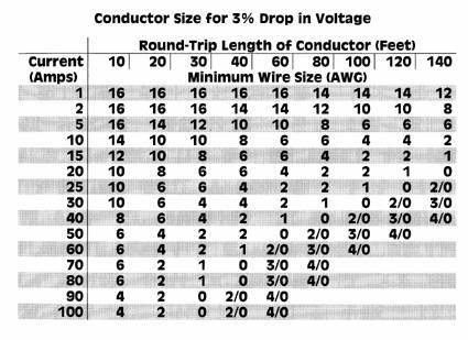
Update 11/15/2018: Here are a few more links for when I was specifically trying to determine a current rating for 22 AWG stranded wire:
I am greatly amused that StackExchange has a section for Electrical Engineering, where I can find people asking dumb questions like mine without having to ask them myself. Here is "Can I pull 2 amps thrugh 22 AWG wire?" This person is also trying to figure out stranded wire, and not really getting an answer aside from an unsourced "it will be fine". But there are a few interesting links from this article. https://electronics.stackexchange.com/questions/350291/can-i-pull-2-amps-through-22-awg-stranded-wire
Here is an interesting table from Gore which seems to be derated for stranded conductors, but it's not explicitly stated: https://www.gore.com/IndustrialCableConfigurator/popup_hfr_wirespecs.html
This Wikipedia article addresses stranded wire by noting the differences with the calculations normally used for solid wire: https://en.wikipedia.org/wiki/American_wire_gauge
Subscribe to:
Posts (Atom)