Tuesday, May 31, 2016

Stranded Wire Size Current Rating

In the old days I had a book to look this stuff up in. It was probably better sourced that what I can find online, but I doubt I could find that book anymore. Here's the results of my searches now.

This page has a super-nice chart and goes down into the wire sizes that I am using. It also does a good job of explaining the sources of the ratings and how conservative they are. It does seem to be specific for solid core wire though, which is a little inconvenient since my wiring is always stranded. http://www.powerstream.com/Wire_Size.htm

This page has a chart that addresses stranded wire. So far I haven't been able to find what source they are using though. It might be from the NEC. http://www.engineeringtoolbox.com/wire-gauges-d_419.html

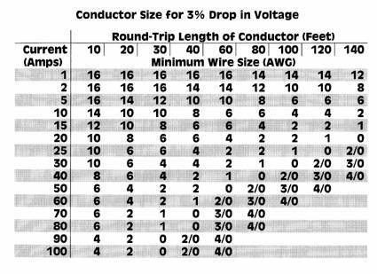
Most of the tables that come up under Google Images are either for house wiring or concerned with a 3% drop round trip for DC 12V. Again, it doesn't seem as though these tables relate to stranded wire. Here are links to a few that might be about solid core wire or not:

http://edsboattips.com/wp-content/uploads/2013/03/voltage-drop-table.jpg

http://www.electric-skateboard.builders/uploads/db1493/original/2X/b/b041f15a19d7d5c9c0d478894688331a5e3d11e9.jpg

This one at least goes down to 1A: https://cdn.sparkfun.com/assets/f/d/2/3/3/51155039ce395f5e3d000002.jpg

Update 11/15/2018: Here are a few more links for when I was specifically trying to determine a current rating for 22 AWG stranded wire:

I am greatly amused that StackExchange has a section for Electrical Engineering, where I can find people asking dumb questions like mine without having to ask them myself. Here is "Can I pull 2 amps thrugh 22 AWG wire?" This person is also trying to figure out stranded wire, and not really getting an answer aside from an unsourced "it will be fine". But there are a few interesting links from this article. https://electronics.stackexchange.com/questions/350291/can-i-pull-2-amps-through-22-awg-stranded-wire

Here is an interesting table from Gore which seems to be derated for stranded conductors, but it's not explicitly stated: https://www.gore.com/IndustrialCableConfigurator/popup_hfr_wirespecs.html

This Wikipedia article addresses stranded wire by noting the differences with the calculations normally used for solid wire: https://en.wikipedia.org/wiki/American_wire_gauge


Leave accumulation

Holidays banked so far:

2/15/2016 M President's Day
5/30/2016 M Memorial Day

Thursday, May 19, 2016

Android move pictures to SD card

A few weeks after we got the android phone, we had managed to fill up its internal memory with photos. So, I needed to learn how to do a few things. 1) Set the photo app to save to the SD card that I'd made certain to buy and install but which wasn't being used by the phone, 2) Move all the photos out of the phone memory to the SD card, and 3) Set the "Gallery" app to show the pictures from the SD card. We're running Android OS 4.2, Jelly Bean.

2) The way that android implements the cut and paste paradigm for files is a little clunky but honestly a whole lot easier than Apple. The key is to find the "My Files" app and then dig through layers to get to the photo folder for the on-board storage. I think that the order of the levels is odd in some way, but just keep going till you get to the DCIM folder (not the Pictures folder, which is just for screen caps or downloads). Then find the button for "select all". Then under the hamburger menu find the "copy" option. Somebody on one of the sites I found recommended doing "Copy" followed by "Delete" rather than "Move" because you never know when something could go wrong in the middle of an operation, potentially causing loss of data. The thing that the various guides didn't prepare me for is that the copy will seem to freeze, but actually it is still going! Patience is required. I ended up trying copy twice which resulted in the files being copied twice. Copies are helpfully renamed "Copy of ..." and I had to go in through the USB port to clean things up.

I looked at several guide pages, and have since lost the original links that I was using, so here are some substitute links to online guides:

This guide is actually better than the first one I found in that the OS looks more like mine: http://innov8tiv.com/how-to-move-pictures-from-gallery-to-sd-card-in-android-galaxy-s5-or-any-other-phone/

I think this was the original guide that I followed: http://www.wikihow.com/Move-Pictures-from-Android-to-SD-Card

3) It wasn't clear at first if there would be a problem getting the Gallery app to check both the on-board memory and the SD card. Several people online had posted about having problems with it, but basically all that is needed is some way to get the app to re-index the phone, which for me seemed to happen naturally, either as a result of time or perhaps a phone reboot.

Here's the google search for the problem showing al the other peoples' pain with this issue: https://www.google.com/#q=android+gallery+show+pictures+from+both+internal+memory+and+sd+card

Wednesday, May 18, 2016

My technique for making assembly drawings

Assembly drawings seem like they should be quick to throw together, because all that needs to be done is to copy and paste the drawings of various parts together. However, the drawings for all the parts are all either done in a variety of different drawing tools or have to be found from vendors, many of whom aren't just giving out free DXF files. So a big wad of different software is needed to put everything together. Here's the list:

Main drawing tool: I would use AutoCAD but it's bloated plus it's expensive and nobody wants to buy it for me. So I'm using DoubleCAD XT which is free for some reason.

To convert front panel drawings: All our front panels are done in Front Panel Designer, which exports to DXF. Astonishingly though, FPD is exporting 3D DXFs, which cause me problems because I am making 2D views and DoubleCAD XT unhelpfully goes nuts trying to render holes that are 3D. The solution is to explode the 3D drawings multiple times in Model Space in DoubleCAD, then select the entire mess and scale Z=0 to flatten the parts. The downside of this is that this results in the tops and bottoms of holes and edges being rendered twice. There's probably a more elegant solution but I haven't had time to figure it out.

To convert board silkscreens to DXF: GerbView is a tool that you can get a trial version of online, but it has proven to be so useful that I had to just buy it. It can be bought from here: http://www.gerbview.com/download.html GerbView can output any layer as PDF, DXF, or other formats. The downside is that the scaling gets mangled; I think that it is outputting the DXF in metric units but I am reading it as English units in DoubleCAD. So to read the DXF that GerbView produces into DoubleCAD requires rescaling before the image can be pasted into my assembly drawing. While searching for tools to view and convert Gerber drawings, I also found GBR2DXF here, and it seemed to be free, but the download process required registering for a password and it seemed like too much information to give out so I didn't try it.

To convert part drawings from PDF to DXF: Many manufacturers will release PDFs of their part drawings, or sometimes just line drawings of their parts. To paste these into my assembly drawing, I have a couple of techniques. The main one is to use a PDF to DXF converter program called Aide PDF to DWG Converter. It uses some kind of algorithm to trace PDFs, and the result is often shaky and poorly aligned if you zoom in but it is possible to then import the DXF and trace it with regular shapes. It has a free trial version but I'm probably also going to buy it. For really clean PDFs of things that were mechanical drawings to begin with, I can just give it the PDF file name, do the conversion, then import the resulting DXF and do cleaning up. It also produces results that are at an incredibly huge scale, so downscaling to convert to 1:1 is also necessary. For drawings where all I have is a JPG or other raster image, I first convert the image to PDF using PrimoPDF or CutePDF.

Some PDFs are shaded or have other features that make them not convert to DXF well. Sometimes I have to make a drawing from a photograph. In those cases, I can feed the drawing into an online tool that produces a black and white raster drawing that looks close enough to a line drawing that I can convert it to PDF and then feed it into the Aide converter. That online tool, oddly enough, is a service for quilters, it is called RapidResizer Stencil Maker. Again, the results of this tool are just approximate enough to produce a DXF that can be cleaned up and traced.


EagleCAD show/hide net names

A couple of links from when I was trying to turn some net names off in the schematic:

Here's how to make a net name show (use the LABEL command or right-click on a net to get label options from the pop-up menu): https://www.element14.com/community/message/107030

Note also, to hide or show a component's name or other built-in attributes, you have to use the "SMASH" command (which is actually an "explode" command to separate the parameters into separate objects that can then have their visibility set.


eagle schematic define socket

Numerous Google searches seem to indicate that Eagle does not have any support for defining whether a part in a schematic is to be socketed, and defining the socket part number. Apparently this is not commonly done anyhow in most schematic capture programs, which seems like a shame. I got around this by simply adding my own attributes to the parts which had sockets, so that when the bill of materials gets generated those attributes show up in their own column. The attribute name that I chose to add where necessary was SOCKET_PN and also SOCKET_DIGIKEY_PN so that the ordering information for the socket would also be stored in the schematic. Naturally, I set "Visible" for these parameters to "off"

Monday, May 16, 2016

How to make isometric drawings in AutoCAD

I wanted to show an isometric drawing of my assembly, but of course I wasn't actually using AutoCAD. It seems from the following link that it might be pretty easy to do it in AutoCAD:

https://autocadtips1.com/2012/07/27/intro-to-isometric-drawing/

It turns out to be super easy to gen up an Isometric view from a 2D 3-view drawing! I found one video that explains everything very well, and then I began to realize that a few of the other links on the subject that I found were saying the same thing.

In short, the procedure is: Take your top view, rotate it by +45 degrees, then scale the Y axis by 0.57735. Take your front view, also rotate it by +45 degrees and scale its X axis by 0.57735, then rotate it by -30 degrees. Take your side view, rotate it by -45 degrees, scale its X axis by 0.57735 and then rotate it by +30 degrees.

Here's the video:

https://www.youtube.com/watch?v=fs71w6UhXiM

Here's a super awesome page that shows exactly the same thing but with words and pictures:

http://www.intellicad.org/articles-and-press-releases/bid/205888/2-D-construction-technique-to-create-an-isometric-view

Here's a completely different way to do isometrics in AutoCAD using the SOLPROF, SOLVIEW, and SOLDRAW commands, which of course are not part of the free knock-off DoubleCAD that I am using:

http://www.maelabs.ucsd.edu/mae_guides/autocad/3d_to_2d.htm

Sunday, May 15, 2016

Bolt Torque tables

Because my assembly instructions have to be very precise, I needed to find actual torque values to put in for every bolt called out in the parts lists. I also expected that there should be some restrictions on the amount of torque one should apply to screws attaching circuit boards to standoffs. Oddly, searching on torque values for circuit board assemblies produced no useful results. It seems that a few other people have had the same assumption, and when they asked the question on forums nobody else thought the question made any sense. Eventually, I found one set of tables, adapted from a Japanese standard, which listed torque values for "electronic assemblies" which seem to be simply half the standard torque values. Here is the link to that table. This table is neat because in addition to the standard and halved values, it lists tighter values for high strength bolts. Also note that aluminum bolts/threads are listed as requiring 0.5 of the standard torque:

https://mdmetric.com/tech/Standard_tightening_torque.pdf

Note that the above table give torques in Newton-meters, logically enough. To convert that to inch lbs, there are sites that have calculators like the following:

http://www.unitconversion.org/energy/newton-meters-to-inch-pounds-conversion.html

That table is from something called the "Tohnichi Torque Handbook" which comes up well in Google searches on its own. Those values are for metric bolts and screws only, however. For English bolts, I got more google hits, strangely:

Here is the one I've been using mostly, because it goes all the way down to #4 screws and gives the values in inch lbs. However, this is just a car enthusiast's blog and doesn't credit the source of the table so I should probably find a better link: http://tr6.danielsonfamily.org/TAStripTest.htm

This table references SAE values, but doesn't apply to anything smaller than 1/4-inch bolts. This is the issue I encountered for most Google hits for English bolt torques: http://www.engineershandbook.com/Tables/torque.htm

However, it looks like another page on the same site does have the smaller sizes, and also lists torques for aluminum: http://www.engineershandbook.com/Tables/torque3.htm

This presentation has a nice table on page 9 which goes all the way down to 4-40, and an appendix that shows how to derive values for yourself using formulae: http://fp.optics.arizona.edu/optomech/Fall14/Notes/18%20Fasteners.pdf